Source-backed payload assembly
Open the box: every major subsystem now has a measured place.
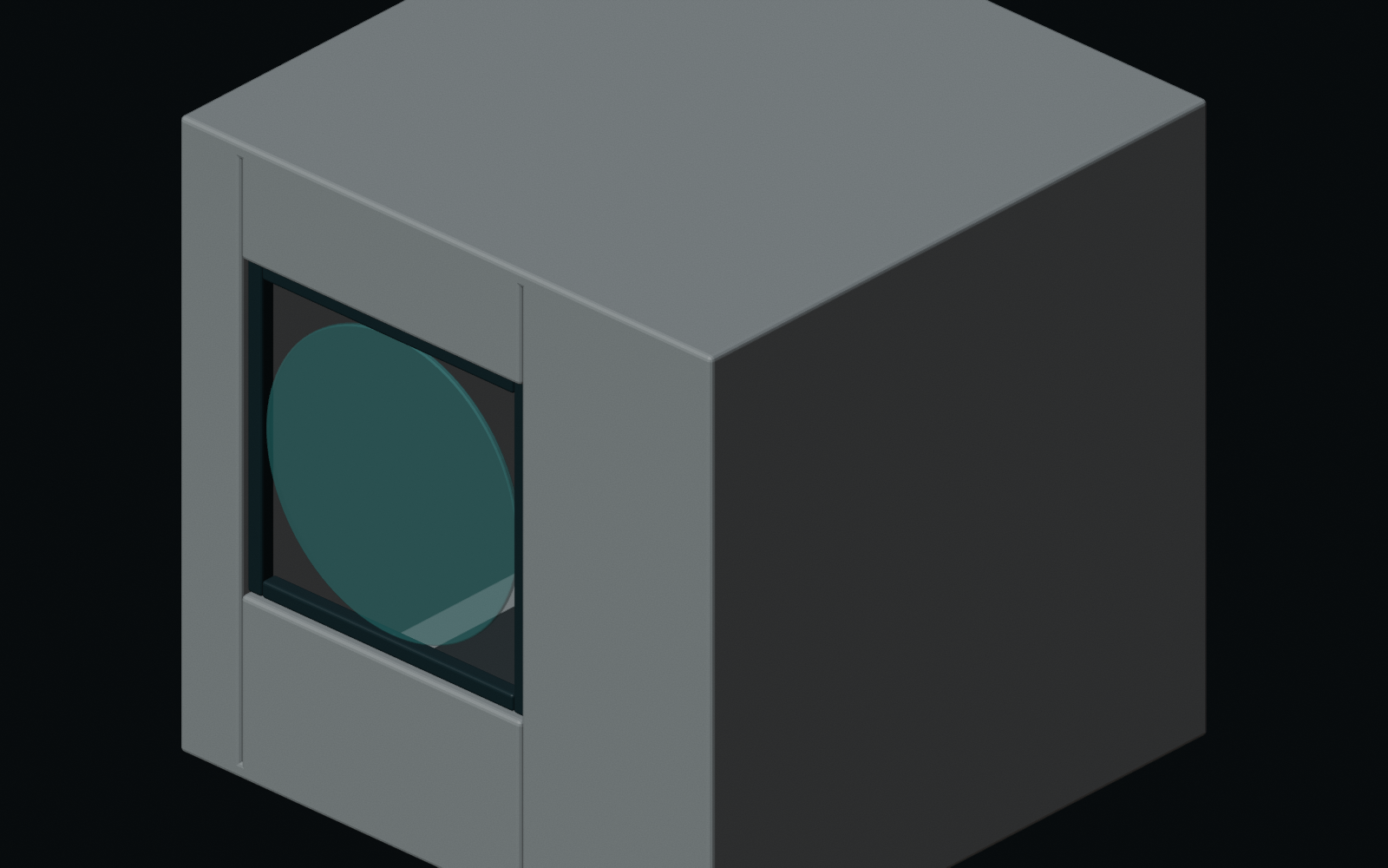
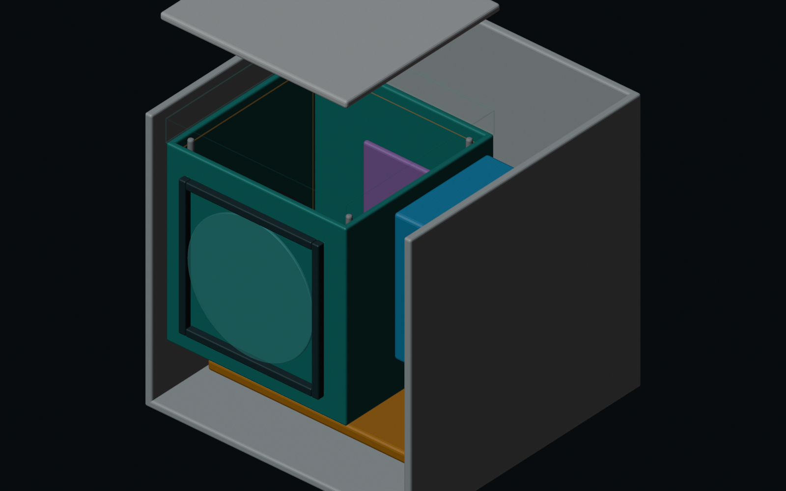
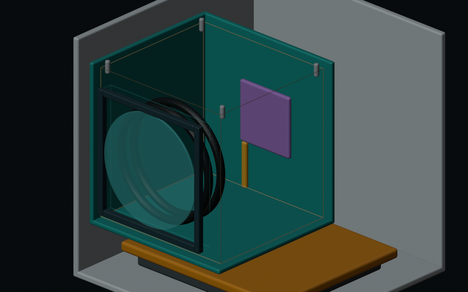
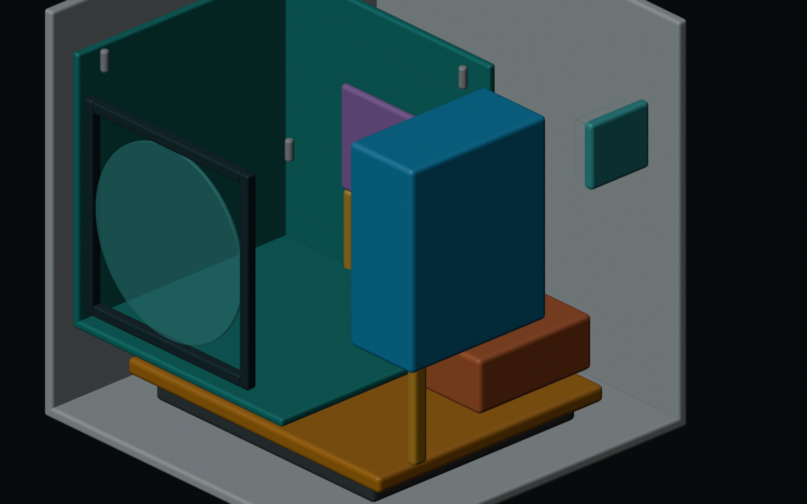
The RFS-075 block model is now visible as five source-matched Blender views: exterior, service interfaces, optical-bay cutaway, electronics/thermal cutaway, and exploded assembly. Every rendered component comes from the committed 148 mm, 1.644 kg assembly source.
Assembly review
The exterior view closes the housing around a serviceable 70 mm-clear LWIR window.
| Subsystem | Mass allocation | Package allocation | Design rule |
|---|---|---|---|
| Optical train, mirror cells, stops, and baffles | 0.32 kg | About 100 mm x 100 mm x 75 mm central optical bay | Leave real clearance around the compact proof span for mounts, blackening, fasteners, and datums. |
| Detector core, carrier, shutter/reference allowance, thermal block | 0.12 kg | About 45 mm x 45 mm x 35 mm detector-side bay | Use the Boson+ lensless path without forgetting carrier, cabling, and reference hardware. |
| Compute, storage, timing, geotag, and interface electronics | 0.22 kg | Side or rear electronics bay | Preserve raw-frame capture, calibration state, alerts, and validation logs onboard. |
| Housing, weather sealing, LWIR window, and forebay | 0.42 kg | Full envelope boundary with wall and seal allowance | Make the window the serviceable contamination boundary for smoke, dust, drizzle, and cleaning marks. |
| Drone adapter, vibration isolation, base plate, and trim | 0.28 kg | Bottom adapter zone | Keep drone brackets separate from the optical datum structure. |
| Thermal spreader, straps, sensors, and passive margin | 0.20 kg | Conductive path to base and shaded housing faces | Start passive and let radiometry decide whether active thermal control is needed. |
| Harness, connectors, fasteners, labels, and field-reference allowance | 0.12 kg | Distributed service allowance | Reserve room for power/data strain relief, bench access, and reference-target handling. |
| Management reserve | 0.32 kg | Unassigned mass and volume margin | Protect the sub-2 kg target from underestimated housing, bracket, and environmental-protection mass. |
Interfaces and cutaways
The five views expose service paths and separate the optical and electronics bays.
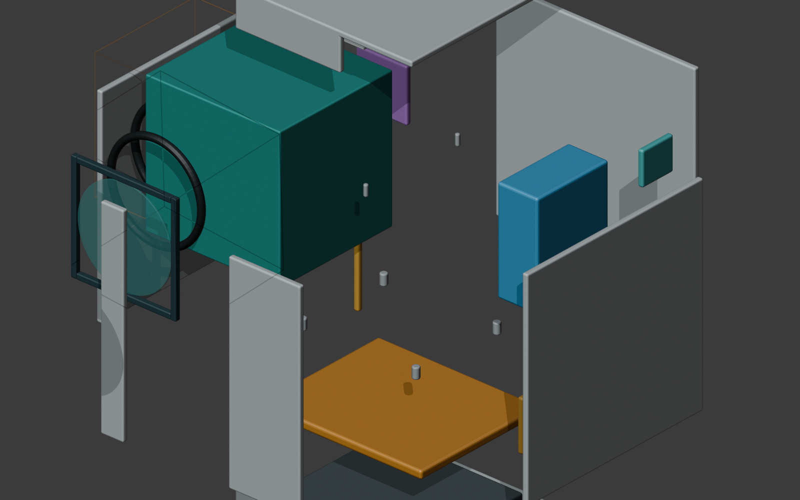
Hash-traced review evidence
The static build fails if the render source or published pixels drift.
The scene description is generated from the versioned RFS-075 assembly, optical-interface record, and mechanical validation result. The static build rechecks those inputs plus all five committed image hashes; changing a source coordinate without refreshing the views becomes a build failure.
The optical bay still consumes a replaceable interface rather than individual mirror coordinates. The wire volume uses the latest failed three-mirror candidate only as an envelope and mass proxy. It is not a depiction of mirror surfaces, a ray trace, or evidence that the candidate passes P2.
These files are engineering-development geometry. They are not CNC-ready, not fabrication-ready, and do not establish optical acceptance, tolerance, sealing, thermal, vibration, or manufacturing release.
Mechanical concept
A sealed optical cassette sits inside a serviceable outer payload.
The first payload layout should separate the precision optical frame from the drone adapter and weather shell. Mirror cells, detector datum, and internal stops belong to a bench-aligned cassette; window service, connector protection, and drone-specific brackets belong to the outer package.
The field concept avoids many operator adjustments. Factory align the cassette, lock the mirrors, leave one controlled detector-focus compensation if needed, and use calibration metadata to flag drift.
Power and thermal path
The first payload budget targets 8-12 W steady operation and holds 15 W as the design ceiling.
Detector and carrier
1 W is reserved for the low-SWaP detector branch plus carrier, interface, and shutter or reference handling.
Compute and storage
5 W supports raw thermal capture, candidate detection, local logging, and metadata stamping.
Interface and telemetry
2 W covers alert packets, status, and integration electronics without assuming continuous high-rate downlink.
Thermal allowance
2 W is reserved for anti-condensation, cold-start, or reference-target stability if field tests need it.
Field environment
The payload response is tied to the fireground exposures that can break thermal evidence.
| Exposure | Payload response | Validation implication |
|---|---|---|
| Vibration and propwash | Use a vibration-isolated adapter, locked mirror cells, strain relief, and a bench-vibration check. | Translate optical sensitivity into acceptance limits for tilt, decentre, and focus shift. |
| Dust, ash, smoke residue, insects, and grass seeds | Put a replaceable or cleanable LWIR-compatible window ahead of the optical cassette. | Record window state, cleaning time, and post-clean reference frames in validation exports. |
| Light rain, humidity, and condensation | Seal the cassette boundary, protect the connector, and reserve anti-condensation power. | Field tests must include humidity notes, window checks, and rejected-frame flags. |
| Sun, hot vehicles, and warm fireground surfaces | Use a light exterior finish, passive conduction to base, and temperature telemetry. | Radiometry tests need warm-housing and cooling-after-flight cases. |
| Cleaning and service handling | Make the window serviceable without disturbing mirror alignment. | Operational procedures should separate window cleaning from optical realignment. |
Assembly guidance
The modeled package now has a reviewable assembly and inspection path.
RFS-076 now exposes the RFS-075 components and service paths in a source-hash-traced review set. The views make packaging decisions inspectable without strengthening the underlying maturity claims.
RFS-077 now records the numbered bill of materials, make/buy split, provisional datum and alignment strategy, assembly order, fastener/access plan, handling, blackening, sealing, inspection, tool, and rework guidance against these views. Optical acceptance and tolerance evidence remain prerequisites for alignment-critical manufacturing files.