RFS-077 · assembly and manufacture
A build sequence reviewers can challenge, with every missing release decision exposed.
The 16 source component families now have a numbered make/buy inventory, provisional datum strategy, assembly order, access plan, handling controls, inspection gates, required tools, and a reversible service path.
Maturity boundary
This is an engineering-development review package, not a manufacturing release.
The generated screen measures a 148 mm cube, 1.643922 kg modelled mass, 0.356078 kg reserve against the 2 kg budget, no axis-aligned interference among the checked components, and no protected-clearance violations.
Passing those screens does not establish buildability, optical alignment, sealing, thermal qualification, vibration survival, or no-vignetting. The optical core is a failed candidate used only as a 92 x 92 x 84 mm envelope and 0.363922 kg mass proxy.
The package is not CNC-ready and not fabrication-ready. Materials, part drawings, tolerances, thread and torque specifications, seals, finishes, and a passing optical prescription are not released.
Numbered bill of materials
Every modelled family has a make/buy route and an explicit release gap.
| Item | Source ID | Assembly item | Make/buy | Model evidence | Release gap |
|---|---|---|---|---|---|
| 01 | outer_enclosure | Weather housing and sealed outer enclosure | Make | 148 mm cube shell; 4 mm model wall; 0.300 kg | Material/process, joints, seal lands, drainage, finish, tolerances, proof test. |
| 02 | optical_cassette | Removable optical cassette frame | Make | 100 x 100 x 95 mm shell; 3 mm model wall; 0.120 kg | Datum faces, mirror-cell interfaces, stiffness, material, tolerances, locking, metrology. |
| 03 | replaceable_optical_core | Optical prescription and mirror-cell assembly | Protected integration item | 92 x 92 x 84 mm keepout; 0.363922 kg proxy | No passing prescription, tolerance budget, mirror cells, coatings, or release. |
| 04 | lwir_window_carrier | Serviceable LWIR window and carrier | Buy + make | 78 x 78 x 4 mm carrier; 70 mm clear; 0.060 kg | Window substrate/coating, retention, carrier, seal, cleanliness, proof method. |
| 05 | detector_mount | Detector core, carrier, and focus mount | Buy + make | 38 x 38 x 4 mm carrier plane; 0.070 kg | Detector selection, focus range, datum, locking, thermal interface, ESD, tolerance. |
| 06 | compute_tray | Compute, storage, timing, and geotag tray | Buy + make | 30 x 74 x 60 mm allocation; 0.160 kg | Electronics selection, tray, connectors, cooling, retention, software, vibration support. |
| 07 | power_tray | Power conversion and interface tray | Buy + make | 30 x 20 x 50 mm allocation; 0.100 kg | Converter/protection hardware, insulation, fusing, wiring, retention, thermal limits. |
| 08 | connector_panel | Protected power/data bulkhead panel | Buy + make | 4 x 24 x 26 mm allocation; 0.030 kg | Connector, pinout, backshell, strain relief, sealing, bonding, cut-out. |
| 09 | drone_adapter | Replaceable adapter and isolation plate | Buy + make | 104 x 8 x 90 mm plate; 0.200 kg | Airframe geometry/loads, isolators, material, fasteners, load path, acceptance. |
| 10 | heat_spreader | Passive base heat spreader | Make | 120 x 6 x 100 mm plate; 0.080 kg | Thermal model, material, flatness, finish, attachment, contact pressure, isolation. |
| 11 | detector_heat_strap | Detector-to-base flexible heat strap | Buy + make | 4 x 45 x 4 mm allocation; 0.0125 kg | Strap, terminals, bend radius, contact treatment, fasteners, thermal acceptance. |
| 12 | compute_heat_strap | Compute-to-base flexible heat strap | Buy + make | 4 x 36 x 6 mm allocation; 0.0125 kg | Strap, terminals, bend radius, contact treatment, fasteners, thermal acceptance. |
| 13 | entrance_baffle | Entrance stray-light baffle ring | Make | 72 mm OD, 62 mm ID, 4 mm length; 0.0125 kg | Material, edge, blackening, witness coupon, tolerance, optical acceptance. |
| 14 | secondary_baffle | Secondary stray-light baffle ring | Make | 72 mm OD, 62 mm ID, 4 mm length; 0.0125 kg | Material, edge, blackening, witness coupon, tolerance, optical acceptance. |
| 15 | service_access_panel | Top cassette service-access panel | Make | 104 x 4 x 99 mm panel; 0.040 kg | Attachment, seal, opening clearance, captive hardware, finish, service-life test. |
| 16 | fasteners_and_harness | Fasteners, harness, labels, and strain relief | Buy + make | Distributed 0.070 kg allocation | Hardware schedule, wire list, labels, routing, clamps, torque, locking, bonding. |
These are source component families, not a final piece-part count. Housing panels, mirror cells, brackets, harness branches, seals, adhesives, isolators, fasteners, and tooling will increase the released part count.
Datum and alignment strategy
Keep optical alignment inside the removable cassette and airframe loads outside it.
Optical datum set
Establish mirror-cell and detector relationships inside the cassette. The weather shell and drone adapter do not carry optical alignment.
Entrance reference
Locate the 70 mm-clear window and 62 mm-ID baffles about the cassette entrance axis. The 3.22 mm radial mechanical allowance is not no-vignetting evidence.
Detector reference
Use the 38 x 38 mm carrier plane as the focus interface. Piston, tip, tilt, decentre, and adjustment range remain unset until tolerance analysis closes.
Housing seat
Insert the cassette through a repeatable, metrology-accessible seat. Exact locating faces, pins, shims, preload, and repeatability criteria remain unresolved.
Load-path separation
Attach the heat spreader and replaceable drone adapter to the outer package without making the airframe interface the sole optical datum.
The source frame uses the payload-centre origin, +X toward the connector, +Y away from the adapter, and +Z from entrance toward detector. Exact datum faces and tolerances require a passing optical prescription.
Assembly order
Build and inspect the cassette on a bench before it enters the outer payload.
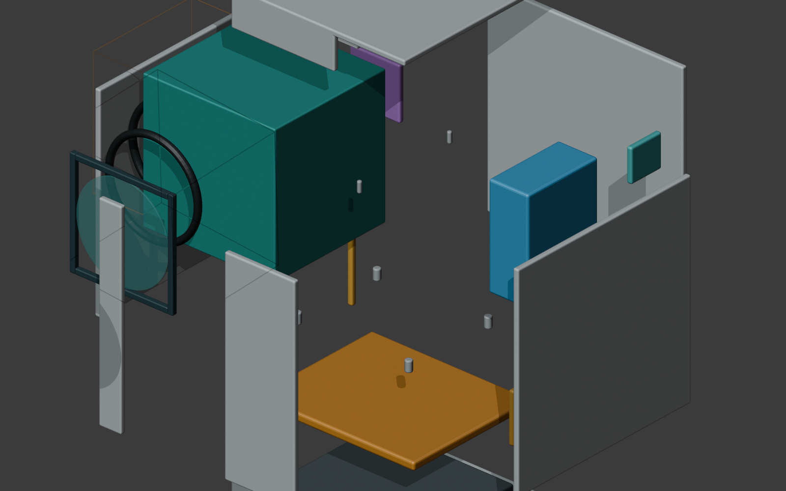
- Verify the release pack. Match revisions and hashes; stop if alignment-critical evidence is missing.
- Prepare custom parts. Deburr, clean, protect interfaces, and accept coating coupons before sensitive integration.
- Prepare the cassette. Inspect datum features and the optical keepout; install accepted, blackened baffles.
- Integrate a later passing optical core. Use released cells and handling instructions; keep covers fitted.
- Install the detector carrier. Use ESD control, record focus state, and connect the released thermal interface.
- Build the load and heat path. Fit spreader and adapter without distorting the cassette seat.
- Install electronics and harness. Preserve backshell clearance, strain relief, and cassette extraction.
- Insert the cassette. Avoid the window, baffles, detector, straps, and harness; verify its datum state.
- Fit window carrier and seals. Confirm the 70 mm clear aperture and service clearance.
- Close and inspect. Record mass, electrical, thermal, seal, clearance, and optical state before aircraft integration.
Fastener and access plan
Eight locations are modelled; most real joints are still absent.
| Group | Source locations | Model geometry | Intended access | Missing release evidence |
|---|---|---|---|---|
| Cassette | cassette_f1 to cassette_f4 | Four 3 mm diameter x 8 mm cylinders, +Y | Top opening and 100 x 12 x 95 mm extraction corridor | Joint stack, thread, tool clearance, preload, locking, torque, repeatability test. |
| Drone adapter | adapter_f1 to adapter_f4 | Four 5 mm diameter x 8 mm cylinders, +Y | Bottom interface with payload removed | Airframe interface, load case, isolator stack, thread, preload, locking, torque. |
Diameter and length describe clearance geometry only. The source has no fasteners for enclosure seams, access panel, window, detector, trays, connector, spreader, straps, baffles, harness clamps, or mirror cells.
Sensitive-hardware handling
Window service is a field boundary; mirrors and detector alignment remain workshop work.
Mirrors
Handle only through released cells or edge fixtures. Never load an optical surface or use an element as an alignment lever; keep protective covers fitted.
Detector
Use an ESD-controlled bench, cap the aperture, record focus/shim state, and prevent its carrier from forcing cassette alignment.
LWIR window
Service without disturbing the cassette, using a later substrate/coating-approved cleaning method. Record cover removal, cleaning, and inspection.
Contamination
Reject trapped particles, uncured coating, seal debris, swarf, fingerprints, and unsupported harness near the optical path.
Baffles, blackening, seals, and heat paths
Finish and environmental steps need witness evidence before sensitive integration.
Baffle and blackening sequence
- Machine and inspect both 72 mm OD / 62 mm ID rings to later released drawings.
- Clean compatibly and mask datum, fastening, thermal, and aperture-control faces.
- Qualify the selected low-reflectance treatment on witness coupons.
- Cure and inspect for coverage, adhesion, shedding, thickness intrusion, and contamination.
- Re-measure each 62 mm bore after coating and re-run optical no-vignetting acceptance when real beams exist.
Sealing and thermal-interface steps
- Select seals and release groove, compression, compatibility, life, and proof requirements.
- Inspect seal lands; record seal batch and installation state.
- Retain the LWIR window without point loading or clear-aperture loss.
- Release heat-contact finish, interface material, contact pressure, and strap bend radii from thermal testing.
- Route straps without loading cassette datums or blocking extraction.
- Perform later leakage/ingress and thermal tests; the current model is neither sealed nor thermally qualified.
Inspection points
Nine gates separate source checks from as-built and optical acceptance.
| Gate | Inspection | Current evidence | Release criterion still needed |
|---|---|---|---|
| IP-01 | Incoming identity and condition | 16 source families | Suppliers, drawings, certificates, serial/lot capture, defect limits. |
| IP-02 | Custom dimensions and interfaces | Model boxes, shells, rings, fastener locations | Tolerances, datums, finish, threads, GD&T, metrology. |
| IP-03 | Cassette datum and optical alignment | Cassette separation and detector-plane concept | Passing prescription, tolerance budget, adjustment, targets, repeatability. |
| IP-04 | Apertures and protected volumes | 70 mm window, 62 mm baffles, four clearances | As-built limits and optical no-vignetting proof. |
| IP-05 | Interference and envelope | AABB screen passes; 148 mm cube | As-built 3D inspection with joints, harness, seals, tolerances. |
| IP-06 | Mass and centre of gravity | 1.643922 kg model; 0.356078 kg reserve | Calibrated as-built mass/CG limits and configuration control. |
| IP-07 | Electrical and thermal interfaces | Tray/strap allocations; 15 W ceiling | Continuity/insulation, sensors, temperature limits, thermal balance. |
| IP-08 | Environmental closure | Serviceable window/panel concept | Ingress, contamination, cleaning, vibration, thermal-cycle criteria. |
| IP-09 | Final optical/radiometric state | No acceptance from mechanical model | Image plane, throughput, no-vignetting, MTF/energy, calibration, focus, post-vibration checks. |
Required tools and facilities
Capability classes are known; exact tool ranges await released hardware.
- Revision-controlled traveller and source/manifest hash checker.
- Clean optical assembly bench, covers, lighting, particle control, and approved cleaning supplies.
- ESD-controlled detector/electronics bench.
- Calibrated datum-appropriate dimensional metrology and aperture gauges.
- Calibrated balance and centre-of-gravity fixture.
- Calibrated torque tools after the fastener schedule defines ranges.
- Electrical continuity, insulation, current-limit, and functional-test tools.
- Temperature logging and thermal-test equipment.
- Leak/ingress test equipment matched to the later requirement.
- Optical alignment and image-quality metrology defined by a passing prescription.
Rework and disassembly path
Preserve the as-found state, remove the cassette cleanly, then repeat downstream gates.
- Record fault, configuration, thermal/calibration state, and as-found optical evidence before disturbance.
- Power down, isolate the aircraft interface, remove the payload, cap connectors, and clean the exterior.
- Open the service panel and retain labels, shims, witness marks, and fasteners by joint.
- Extract the cassette through its protected corridor using a released fixture; do not pull on detector, straps, baffles, or harness.
- Service the window independently. Mirror, detector, baffle, focus, or datum work returns to the controlled workshop.
- Replace non-reusable seals, locking devices, interface materials, and contamination controls.
- Reassemble from the applicable step and repeat all downstream inspection, alignment, and radiometric gates.
Manufacturing-release gaps
The guide exposes what must close before the package can become build hardware.
Optical release
Passing prescription, tolerance budget, mirror cells, detector-focus design, alignment method, and import-ready exchange.
Part release
Part-level solids/drawings, materials, finishes, coatings, datum schemes, tolerances, stack analysis, and metrology.
Joint and service release
Fasteners, seals, adhesives, harness, thermal interfaces, tool access, torque, locking, repeatability, and inspection records.
Qualification and authority
Airframe loads/CG, optical, thermal, vibration, ingress, electrical, contamination, service, and human engineering approval.
RFS-078 remains blocked until a passing prescription and tolerance evidence exist. This guide does not unblock CNC-ready optical or alignment-critical manufacturing files.